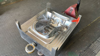
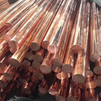
Copper Blocks for Mould Bases – Durable Solutions for Precision Manufacturing Applications
From years of working in precision machining shops and mold making environments, I've come to understand the immense impact material selection can have on performance, longevity, and production output. One topic that continues to impress me — both from a technical and practical standpoint — is the utilization of copper blocks in mould base assembly.
In particular, when crafting complex dies or managing high tolerance projects, having reliable mold base materials with superior thermal conductivity and workability isn't just advantageous — it's essential. That’s why professionals in manufacturing often look to incorporate copper blocks within their systems for improved stability and heat distribution.
Difference Between Conventional Steel Moulding and Copper Enhanced Base Shoe Molding Designs
The primary advantage of using Base shoe molding systems that are bolstered by insert blocks of copper lies in how these materials respond under dynamic pressure and repetitive thermal cycles during forming operations like injection molding or forging tools.
| Mold Material Type | Thermal Conductivity (W/m•K) | Maintenance Interval Cycle | Lifespan Expectancy |
|---|---|---|---|
| Convetional Carbon Steel Base | ~43–47 | 25k-60k cycle marks | 12 - 38 months |
| CNC Machined Brass Inserts | ~110-128 | N/A – embedded cooling design lowers wear | Dependant on tool design but generally > 2 years if not corroded |
| Solid Block High Density Pure Copper Inserts | 385+ | Held together better with reduced need for maintenance up to 90% depending on use case scenarios and part volume. | Exceeds five-years under normal production parameters in ideal climate conditions. |
This comparison clearly demonstrates copper’s dominance regarding conductivity and long term viability over older steel based setups.
Why You May Consider Integrating Copper Insert Blocks into your Customized Mould Base Design?
- Reduces internal stress fractures during cyclic loading due to superior elasticity.
- Rapid dispersion of hot spots improves cycle times in thermoplastic processes by as much as 18%.
- Erosion resistant nature minimises polishing intervals — a major bonus for those of us stuck with legacy machines lacking automated surface treatments.
- The inherent malleability simplifies hand-finishing tasks during prototype testing phase without fear of structural deformation or loss of hardness over time unlike most mild alloys used commonly across smaller outfits and educational training facilities.
How to Copper Plate Mold Sections Without Compromising Surface Integrity
I won’t go into the full electroplating mechanics here, but let me share some of what I’ve applied directly myself while troubleshooting overheating mold assemblies in high throughput runs. If you're asking "how to copper plate" critical mold surfaces for improved wear resistance — and more importantly — thermal dissipation, consider a few key tips:
- Clean every inch of the base prior plating – even minor oil residue can cause pinholes in final plated coatings leading to premature breakdown under operating temps above 200 degrees Fahrenheit.
- If using submerged electrolyte systems (like barrel plating baths), verify all electrical connections along cathodic contact zones; voltage imbalance could ruin uniform build-up patterns which might not be visible initially post drying phase but appear later during operation under actual processing load.
- Treating pre-coatings layers with acid rinses help prevent oxidation at sub layer boundaries — especially important when dealing with iron substrates being overlaid since iron oxides are conductive and promote corrosion initiation beneath plated copper caps, particularly in areas exposed frequently to moisture carrying cooling liquids.
- Fabrication notes — remember to always account for microstructural expansion of the deposit when determining dimensional tolerances for insertion mating surfaces, typically copper buildup is .018" to .023" thick per side when flash-plating followed by finishing polish cuts. Some folks underestimate this and face alignment mismatches later on.
In practice? The last thing you need during trial runs or pilot production shifts is a misalignment error traced back to improper plating preparation protocols on custom inserts you paid thousands to machine out of premium block stock material just weeks before!
Machinability Challenges with Solid Form Copper vs Alloy Versions – My First Hand Insights.
Working with pure, high-conductivity copper (ASTM 11000 grade, etc) poses unique machining considerations. Unlike typical CDA 110 or 145 alloys I’ve run into during past projects, solid forms demand slower speeds unless you’re willing deal with galling during boring operations—especially noticeable on inner bore reaming sequences.
To minimize built-up edge development and maintain finish quality between successive cuts, here are a few steps from personal experience in CNC lathe and milling spindle usage:
- Select cutting bits specifically marked non ferrouss material engagement such as PCD-tipped carbide cutters for best results;
- If you find chatter appearing despite correct speed adjustments check rigidity on work clamps and adjust collets if chuck grip causes vibrations through tool bit tip area,
- Avoid excessive flood lubriction; water-based emulsions tend to leave oxidation traces overtime in storage so many turn towards dry air or mist coolant systems;
- Lastly, deburring operations on machined edges take longer then expected sometimes and needs manual smoothing post process. Don’t rush this step! Otherwise burring can damage seals when assembled against plastic runners inside mold chamber regions causing costly leak paths or uneven resin filling behavior.
There may be days you wish you never tried integrating copper components... but once everything works properly? It feels satisfyingly worth all the trouble.
The Environmental Angle: Sustainability and Recycling Potentional
Another thing my experience has shown is that the recyclability of copper shouldn't be understated. With increased regulations coming in various countries around emissions and materials reuse — copper remains a favorite among environmental teams in big firms trying to comply green certification standards.
We often get asked, can damaged copper bases get salvaged after extensive use periods in corrosive mold rooms? In short yes, melting down and recasting old sections is very common practice among foundries we partner with on long run parts supply arrangements.
This gives us added leverage negotiating pricing since customers appreciate knowing they have future recovery options available. So don’t throw old scrap blocks out until verifying potential reuse or metal reclaim possibilities – trust me, it does add up on quarterly cost reports!
If you handle multiple clients and manage inventory flow in large mold manufacturing hubs where space is tight or cash flow fluctuates regularly — keeping recycled raw stocks helps buffer against material cost swings tied heavily to global market indices and supplier lead-time variations.
Potential Disadvantages & Real Cost Comparissons
Still, it'd be foolish of us to only highlight positives without acknowledging drawbacks. Here's an honest rundown of issues we encountered during early copper-based base prototyping efforts that caused some headscractching among seasoned team leads.
| Challnege Description | Type of Copper Affected? | Observed Consequences During Early Tests/Adoption Phase | Possible Solutions Based on Actual Fixes |
| Mold warpage due to thermal stress mismatch | Hard rolled copper slab stock inserts | Expansion gaps emerged between adjacent hardened frame members creating microleaks | Increased joint tolerance compensation in assembly blueprints, added secondary epoxy sealing lines along seams and grove points for insulation redundancy |
| Machining burn effect during aggressive tool paths | Annealed cast copper segments (not fully heat treated) | localized melting spots noticed on thin profile ribs reducing accuracy measurements upon initial tests | Lubricant mixture revised using graphite blends instead traditional mineral based alternatives for less heat retention during shaping procedures |
The bottomline? Initial costs per pound make people blink — sure enough copper isn't budget-friendly, but the lifetime gains offset this investment hands down. If you think ahead, it becomes an efficient play financially in addition to the technical boons. Still there must always careful planning upfront when integrating any foreign material in traditional workflow otherwise you will end wasting resources fixing mistakes made early stages design rather than optimizing late phases deployment timelines efficiently.
Maintaining Copper Based Tools Long-Term – Practical Tips Based On Industrial Maintenance Protocols
I’ll let y'all in on some tricks developed during late night emergency tool repairs following unexpected production halts related to mold contamination and poor upkeep practices...
- Visual inspection for oxidisation streak lines forming along water channel passages inside core and cavity regions;
- Test continuity using portable IR thermometer probes along suspected cooling channel intersections with base copper inserts;
- Create basic cleaning routine schedule that includes descaling solution washdown for internal fluid circuits every ~quarterly period especially if located near seaside factories facing elevated humidity problems year round (which seems like more and more locations lately);
Final Conclusion – Worth the Investment For Those Comitted To Superior Quality And Extended Operational Cycles
Looking back now at where we began versus the efficiency improvements observed today — incorporating durable, well engineered **copper inserts** into molded tooling designs was one of our best strategic choices. Not just in terms of performance benefits like reduced downtime from thermal failures or less rework required per lot batch during QC phases—but in sustainability and long-term ROI calculations too.
It’s true — getting setup right involves meticulous prep, careful material handling and ongoing maintenance commitment… But for serious operations where consistent output quality matters — and who aim to scale beyond standard mold industry standards — going with innovative methods like integrating high-quality copper blocks in mold foundation layers isn’t just worth consideration.
In reality? Its a game changing option worth adopting sooner than later.
Remember, investing time upfront to perfect the copper-mold interaction can literally mean fewer tool breakdown calls at inconvenient hours — a peace of mind I know every experienced production leader values dearly at 3AM!


