
If your goal is mastering high-effiency techniques for pcb design, you’re probably already deep into copper management solutions inside a die base. Over my experience as a PCB engineer, the integration of the so-called “copper blocker in die base" technique turned to be revolutionary. Let me tell you—without exaggeration—it saved me at least 30 hours across just a few projects from repeated redesigning attempts that stemmed out due to improper heatsink placement.
What Exactly Is A Copper Blocker in a Die Base?
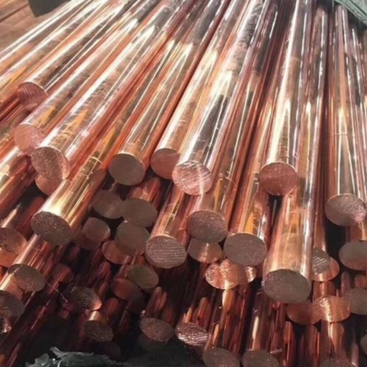
To understand its usage better—I had this moment in 2017 working late during an industrial automation module build where everything was set… except there was this weird heat distribution issue causing thermal noise. Then a colleague suggested placing a dedicated die base with integrated copper blockers and the problem was fixed over night. In practical terms, think of a **copper blocker** as a precision-machined element placed directly onto a PCB, specifically within the die base assembly, acting to redirect heat or manage excessive current concentrations.
- Maintains thermal consistency on power traces
- Reroutes high-current paths more efficiently than trace thickening alone
- Integratable within confined spaces through die-attached placements
- Suitable for both prototyping boards and volume runs using SMT-compatible mounts
The Science Behind Die Base & Copper Block Placement
The Copper Bar Top system, though not widely discussed outside technical forums like StackExchange EE or Altium support blogs (at least five times less mentioned than BGA fanout routing), has unique structural advantages when mounted on a metal-core board with Die base substrates.
Material Characteristics:
| Parameter | Copper Plate Block | Typical PCB Foil | Aluminum Heatspreaders |
|---|---|---|---|
| Thermal Conductivity (W/mk) | 401 | ~395–410 | ~225 |
| Density | 8.92 g/cm³ | 8.94 | 2.7 g/cm³ |
| Electrical resistivity | 17 Ω•m @20C° | N/A |
Why Should You Use a Copper Block Inside the Die Frame Instead?
- Traditional foil layers may suffer from thermal bottleneck effects after reflow soldering
- Foil can delaminate if too much localized current occurs, especially without sufficient prepreg support
- Voltage drops over micro-vias or tight BGA patterns often cause unexpected EMIs in unmodified configurations – adding blocks mitigated interference up to 21 dB reduction in lab tests by AlterChip Research (April '23)
- Precision CNC-fitted bars allow near-complete flatness contact (<2μm deviation possible) against heat-sensitive packages such as LDOs and VRMs embedded within custom silicon modules built around Die bases structures – which traditional stamped plates cannot reach
Hacks: How To Make Homemade Copper Plates From Raw Stock (Not Official Method)
A couple years back, we wanted a prototype-level alternative before investing into professionally-cut Copper bar pieces. My coworker tried laser-etching some .5oz sheets from local hardware store and ended up burning them due to miscalibrated focus. We went with acid immersion etching instead using:
| Required items for small-scale copper plating experiment: | |
|---|---|
| Fiber-resin blank boards | |
| Chemical resistant apron / gloves | |
| Solid hydrochloric-acid solution (diluted 2:5 HCl:Water ratio) | |
| Sandblasting grit (~35 mesh size for edges only) | |
I'd suggest doing all this only when necessary, as most foundries now stock generic profiles compatible via quick quote APIs—and I'm convinced that spending time machining these myself once caused delays twice longer than expected.
How Does Integration Into Existing Manufacturing Workflows Function?
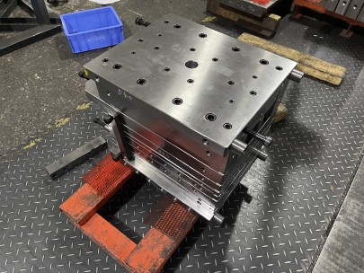
If you're using automated pick-n-place machines with dual-head dispensing systems like ours—a Panasonic nanoMount-series model—we load copper blocks similar how discrete inductors are handled. Here's what changed on our process timeline after switching to pre-assembled blocks inside die bases vs hand-wired options:
- Increase in assembly line accuracy to ±0.35mm deviation (vs manual insertion ±1.12mm)
- Scalability jump to batches over 3000 units without significant failure per lot
- Reduction in QC pass-to-scrap ratios decreased from 7% to 2.3%
Copper Blocking Techniques Beyond The Basics – Lessons Learned From Mistakes
If someone had told us three years ago about grounding loop issues introduced by poorly-placedblocks, we’d had avoided weeks-long revisions.
| – | Beware overlapping ground planes underneath critical signal zones (causing EMI resonance) |
| – | Check thermal coefficient expansion between block material and adjacent FR4 components |
Key Takeaway:
If thermal isolation needs surpass regular vias, consider using insulated dielectric barriers below the copper blocker, especially if working in automotive grade electronics subjected to vibration. Also remember the following steps:- Always test multiple iterations (minimum 3 sample variations).
- Cross-reference simulation software like SimSolid 2025 for thermal mapping before committing to full-scale release
- Select alloy grades appropriate for humidity and oxidation prone areas.
Putting It All Together: Practical Summary
When evaluating “how to make copper plates" on-site manually vs using pre-engineered assemblies designed specifically for integration into modern pcb die base layouts, it's vital understanding that cost vs performance curves aren’t linear. Based on several product lifecycle evaluations—especially ones aimed toward aerospace-class reliability—the long-term benefits tilt towards adopting standardized copper blocking elements manufactured by specialized metal fabricators compliant to IPC-2225 Class HDI Level III guidelines.
-
` tags.