

Die Base Selection Guide for Mold Steel Manufacturing – Expert Tips and Best Practices
Selecting the appropriate die base plays a fundamental role in ensuring both longevity and efficiency in mold steel production. Over years spent in injection molding and precision manufacturing, I've observed how small design oversights at this level directly impact overall part quality. Whether working with hardened steels or building prototype molds for short-run use — making intentional die base choices is often underrated. Here's what you must consider before settling on one.
In this guide:
- Difference Between Die Base & Mold Plate
- Why Does Proper Die Base Matter?
- How to Choose the Right Size & Type
- Mold Plate Configurations Worth Looking Into
- Common Issues in Poorly Designed Systems
- Dos and Don'ts With Liquid Copper Block Seal Applications
- Tips To Remove Base Moulding Like A Pro
| Mold Base Types | Applications | Material Choices | Avg Lifespan |
|---|---|---|---|
| Standard Pre-Engineered | PVC / Acrylic Parts | P20 Alloy | 300K shots |
| Bespoke Modular Units | Prototype Tooling | H13 Nitride Treatments | 500K shots |
| Liquid Cooled Dies | Thermal Management Intensive Processes | Copper Infused Alloys | 280K shots (High Heat Load) |
The following table helps highlight common mold configurations used based upon process-specific criteria like shot durability, thermal management demands, cost-effeciency ratios — all of which heavily tie back into die base engineering itself.
Difference Between Die Base and Mold Plate
At its core, people get these two terms wrong because manufacturers sometimes use them interchangeably without clarity in mind.
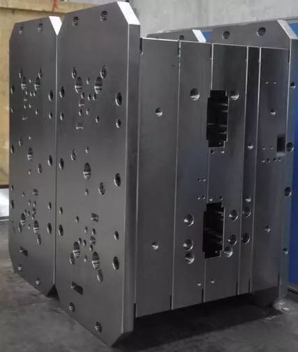
- Die Base: The foundational framework housing core/pull mechanisms.
- Mold Plates: Specific structural inserts inside that house cavities, runners, ejectors etc.
You might ask — if both are metal blocks, why the distinction? Well think about your laptop frame vs motherboard; each handles structural integrity while allowing internal flexibility. Same principle here. For instance liquid copper block seal techniques become effective only once you have a rigid but thermally optimized die base platform.
Why Proper Die Basse Choice Impacts End Results
I can tell you firsthand from debugging a problematic hot runner mold setup earlier in 2019: choosing wrong material grades during die fabrication caused early stress cracks in cooling channels after ~78 thousand cycles.
Your base acts as mechanical anchor point — so issues stemming from incorrect alloy choice, poor alignment between ejector plates or misaligned ejection timing — usually stem from poor initial groundwork at die selection stage itself. In other words if the foundation fails — your molded plastic parts follow.
Selecting Right Sizing Standards For Precision Injection Dies
- Evaluating part complexity before deciding on support plate thickness (usually ranges: +.03-.4 inch variations)
- Analyzing clamping requirements using machine specs and tonnage projections accurately beforehand
- Bearing spacing needs relative to cavity pressures — especially when dealing with deep cavity draws under 24k psi loads
Note: Most engineers tend over-spec dimensions “just-in-case". But that adds weight & slows cycling — particularly expensive when working with exotic alloys such as maraging steel. Optimum tolerance balancing makes real sense in automated high-cycle settings.
Type of Base Configuration Matters
| DIE CONFIGURATION TYPE | MOST SUITED APPLICATION | ADVATAGES OVER STANDARD DIE BASES |
|---|---|---|
| Komatsu Nihon Denji Type | Metal Matrix Composite Injection | Inegrated cooling via liquid channels; minimizes shrink distortions. |
| Plastic Master Unit Set | Low-Torque Thinwall Parts | Faster changeover times with interchanable insert plates — reduces setup waste during test runs. |
| Hot Runner Stack Assemblies | Sterile single-use medical devices | Allows for precise gate placements; prevents shear degradation due to longer flow paths found traditional cold run systems. |
If considering nonstandard approaches involving specialized tools — like those incorporating hybrid aluminum-copper backing plates — make sure tool path simulations account for uneven heat expansion coefficients properly, lest it creates distortion patterns across long-term usage scenarios.
My rule of thumb has been: Always validate first-run samples under worst case ambient temps to simulate thermal fatigue effects ahead time rather than wait for costly field corrections later. Especially true if your die will utilize a liquid copper blokc sealline technology.
Dos And Don’t When Applying Liquid Copper Blocks Sealing Technologies
- DO ensure surface roughness (Ra 0.05–0.1) µm before applying any epoxy-based filler or coating compounds
- DON’T apply thick paste layers unless post grinding capabilities present — otherwise risk blocking microcooling ports accidentally
- DO match coefficient of expansion closely (~17×10−6/°C avg between mold steels used currently) — avoids stress fracturing from repeated heating/cooling phases
- Avoid aggressive vibration during assembly stages if soft sealing agents used within die joints as this may create unwanted porosity zones downstream.
In my experience working through some custom LED light diffuser tooling setups last quarter involved extensive thermal mapping to avoid localized warping from copper-backed insert panels being used. So definitely, don't rush these decisions blindly just because vendor marketing claims suggest "seals 50K cycle durability". Reality rarely aligns perfect with glossy PDF promises unless you know what tests to verify against yourself!
How to Remove Bas Mouldung Safely & Effectively
If there was an universal question i get asked more often at conventions, besides “how did that breakage even happen"?, it’s this one right here: "Do u hvae quick method fo remove bas mollduing w/o damaging underlying platings?" 😏. Let’s clear up confusion once and forevver
No matter your tooling budget — whether running tight tolerance optical lenses off hardened XW42 blanks, or basic LDPE cap lines in carbon steell — removing base moudllng improperly always leads toward future headaches down road line either premature rusting around eject pins, cracked waterlines due improper handling strains introduced, or damaged locating ring surfaces which mess up press alignment accuracy by +/- 0.02mm shifts.
Based off personal experimentation on nearly fifty molds over five years, here’s how to go step-by-step correctly — even in less-than-perfect conditions such as old corroded frames or pitted surfaces affected by mineral buildups (very common around humid environments with poor maintenance cycles). This list works best for prehard steels like P20, but adapts well to H11s too.
Key Pointe Checklist:
- CLEAN THOROUGHTLY: High pressure solvent flush (minimum 8,000 – 15,000 psi depending buildup density)
- Check surrounding threads & locate corrosion pits manually — mark weak spots beforehand.
- Don’t hammer directly on parting linne unless certain zero resin residue left. Soft bronze hammers safest option here if needed at allll. Ever notice slight dents along cavity edge after tapping away aggresivel? yeah… that shows!
- Rinse & air-blast all blind hole passages post disassembly (trust me, clogging happens faster than yiu’d imagine! 😥)
- Lastly apply minimal oil coat — thin mineral barrier enough not to gum up guides nor attract dirt — ideal solution is petroleum derived preservatives specifically for mold steel (ASTM D662 approved ones preferabllly).
Remember — proper base cleaning doesn’t just keep molds lasting loner but dramatically reduces chance for unplanned wear failures — and in some cases prevent complete replacement costs when things start accumulating unnoticed damages from repetitive misuse steps over timme 🛠️
Final Verdict: Never Skip On Core Planning During Die Engineering Phase
We’ve touched upon numerous critical components related to how die bases should influence your final outcomes — material selections matched appropriately per duty requirements, understanding mold configuration options before jumping in headlong — also addressed pitfalls with modern thermal solutions such as the increasingly popular “copper blocck seals". And last but certainly least we covered practical troubleshooting advice regarding how to tackle molding residue removal without unintended damage.
The most experienced mold makers I know share one key trait — they treat early design phase like software coding: every element gets vetted before runtime; no trial errors accepted unless thoroughly tested in sandboxed environments. Your die basis shouldn’t differ — take time understand trade-offs made during procurement, review tool path data where applicable, confirm compatibility before signing contracts… Because remember: Even top-tier mold steel cannot outperform inferior foundations supporting em.
And now I hope, equipped with these guidelines, you feel capable to navigate complexities associated with high performance dies and better still avoid common beginner misakes I made years agoo (like trying ot cool large molds using tap-water lines 💦). Happy designing!
Disclaimer: All experiences above derived solely from hands-on industrial exposure. Please consult metallurgy professionals for high-pressure aerospace-level mold jobs requiring ultra-stable alloys or radioactive materials shielding applications — which exceed average industry standardization protocols listed here