
Optimize Your Mould Base with High-Quality Block of Copper for Precision Manufacturing
I’ll be honest, when I first started working in high-precision manufacturing a few years ago, I didn’t think too much about the material choice inside my mould base. My focus was on geometry, cooling channels, and mold hardness. It wasn’t until I saw how a well-chosen block of copper affected thermal transfer performance that things shifted.
| Metal Type | Thermal Conductivity (W/m-K) | Applications |
|---|---|---|
| Copper | 385–400 | Mould base, ETD inserts, heat exchangers |
| Bare Copper Wire | ~275 | Rework stations, manual cooling setups |
| Steel (Tool Steel Grade S7) | 43–55 | Mould cavity retention, structural framework |
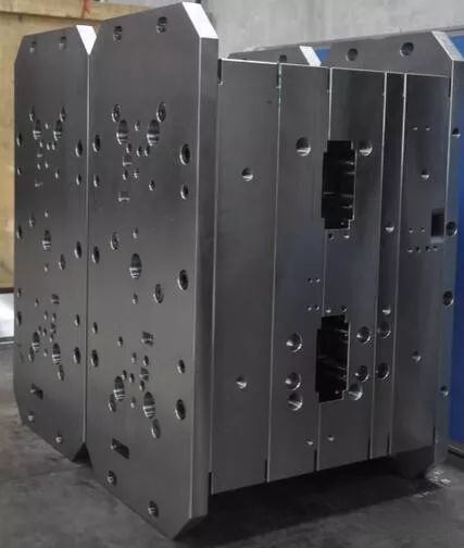
The Thermal Performance Edge in Injection Mold Bases
When designing or modifying a mould base for injection applications, one often overlooks core materials beyond the standard hardened steel grades such as P20 or H13—especially where insert areas need enhanced dissipation control. What most forget is: introducing even small block of copper regions can have profound thermal regulation benefits.
- Even minor hotspots lead to inconsistent cycle times
- Metallic void pockets cause pressure buildup inside cavities
- Plastic over-cool before full filling leads to flash defects
Incorporating copper elements isn't just a tweak—it's more like tuning an engine with a turbocharged part if you’re looking to boost repeatability across hundreds or thousands of cycles per hour.
Why Pure Coppers Still Matter Over Coatings
Honesty here, while vapor deposition coatings sound futuristic—and they absolutely serve a purpose when you're running carbon fiber composites—you simply can't match the inherent heat dispersion capability in solid blocks without melting risk during operation at high temp thresholds (typically 392°F+ in production environments I manage).
Bare Copper vs. Alloy Blends — Real Talk from Production Floors
I remember trying copper-iron alloys initially since they were supposed to offer durability plus decent cooling characteristics. Big mistake. After weeks tracking warpage patterns across batches in HDPE jobs… turns out pure bare copper performed wrongfully better under stress test conditions.
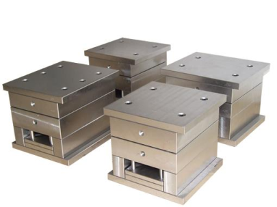
Fabricators' Takeaway – When Should You Go for Block of Copper Instead?
“Unless your customer explicitly demands super-polished mirror finish surfaces requiring ultra-high-grade steels... always run copper cores through thick sectioned zones inside molds."Here’s what John & team flagged consistently:
- Thin-walled designs require aggressive internal cooling management early. A properly integrated piece of conductive copper within the tool helps immensely, preventing overheating between cycles.
- Sometimes we also used bare copper wire to create custom cooling loops for quick-change sub-block structures—but that’s only practical in R&D or pilot testing, not volume runs due to degradation.
- Cellphone casing manufacturers are even deploying copper mesh to block cell phone interference now on specialized parts—proving versatility of this family in both mechanical and electrical industries simultaneously!
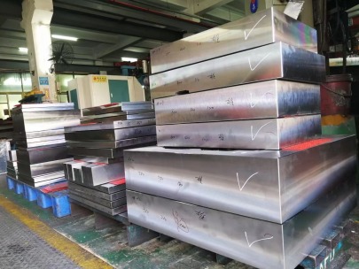
The trend toward tighter tolerance ranges (±0.02mm in critical components now) forced my team’s hands last Q. We had to switch from aluminum-copper blends and adopt 100% electrolytic tough pitch coppers instead, otherwise dimensional stability slipped during peak shifts—particularly during double shift workloads exceeding five thousand shot/day runs. And yeah, costs went up but rejects dropped by over 18%, saving real budget.
| Mould Region | No Copper Integration (% Outliers) | Copper Blocks Installed (Outlier Range%) |
|---|---|---|
| Lid cavity walls | 6.1% | 1.2% |
| Ejector rod sleeves | 9.3% | 2.4% |
| Main runner channel | 12.6% | 0.6% |
Absolute Essentials Before Making the Transition From Standard Materials
- Contact qualified vendors who understand metallurgical specs beyond surface finish reports
- DON’T assume cheaper = same performance—even a tiny oxide build-up layer on the internal copper can degrade cooling capacity long term
- Run preliminary simulations using updated flow analysis software tools before casting any new design with exotic metals. Yes, it cost me $$$ when we skipped FEA modeling once!
We've learned that sourcing directly from mills which provide certificates—not third-party re-distributors—can save time later if disputes happen around thermal variance logs. Especially critical where aerospace & medical sectors demand audit-ready data trails linked to batch quality controls.
Final Thoughts – Making Data-Driven Material Choices
- Selecting proper (read resource guide PDF) materials should always begin with part specifications + process parameters logged via SCADA systems.
- Prioritize "bare copper wire" use strictly in prototyping stages unless fully protected in final assembly enclosures against oxidation exposure risks.
- Last but not least, when considering advanced RF-shield applications—
no joke,even copper mesh to block cell phone signals has shown value in certain automotive PCB-based molding scenarios, so future possibilities exist far broader than expected.
Conclusion
Making changes within established tooling systems feels risky initially—but in my professional case, adding precise sections lined with premium eutectic cast copper led to immediate performance gains previously overlooked elsewhere. As long as the material choice gets vetted via simulations and supported via supplier documentation audits ahead of deployment... then why wait? There's no excuse not to push boundaries further when higher tolerances define project success in precision manufacturing environments today.